Figure 1 from Counterclockwise and Clockwise Rotation of QRS

Figure 1. Scheme for no rotation, counterclockwise rotation, and clockwise rotation of QRS transition zone. - "Counterclockwise and Clockwise Rotation of QRS Transitional Zone: Prospective Correlates of Change and Time‐Varying Associations With Cardiovascular Outcomes"
Assessment of the Rotation Motion at the Papillary Muscle Short-Axis Plane with Normal Subjects by Two-Dimensional Speckle Tracking Imaging: A Basic Clinical Study

Counterclockwise Rotation Common Electrocardiogram Phenomenon Which Stock Illustration 2288503159
Frontiers Dyssynchronous Left Ventricular Activation is Insufficient for the Breakdown of Wringing Rotation
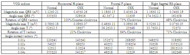
Cardiac Syndrome X Electrocardiographic Patterns Using Signal-Averaged Orthogonal Leads and VCG Indices

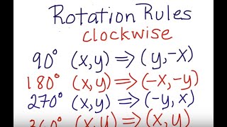
Solved Write a rule to describe the transformation. A.

Rotate a figure 90 degrees counter clockwise about the origin
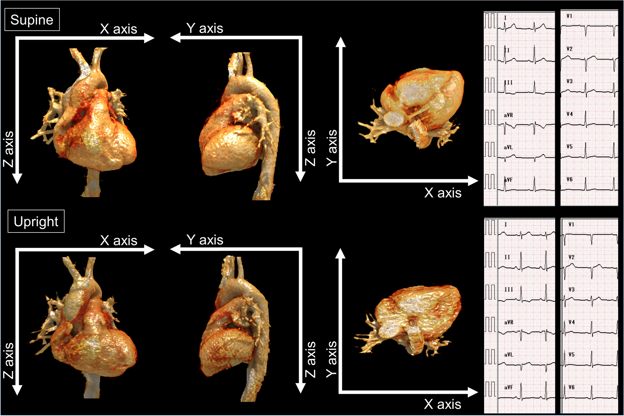
Anatomical cardiac and electrocardiographic axes correlate in both upright and supine positions: an upright/supine CT study
Chest Leads Amplitude Ratio Wave Wave Greater Leads Called Counterclockwise Stock Photo by ©asia11m 650704576
JCM, Free Full-Text

JaypeeDigital
4: ECG Interpretation

Figure 2 from Counterclockwise and Clockwise Rotation of QRS Transitional Zone: Prospective Correlates of Change and Time‐Varying Associations With Cardiovascular Outcomes

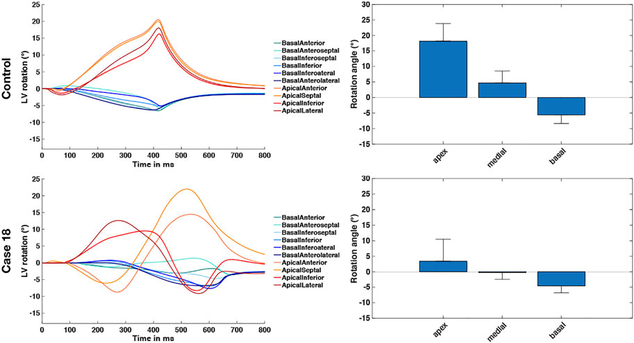
Rotation of LV base and apex during the different phases of the cardiac

CGT 5 G 7a, PDF, Cartesian Coordinate System

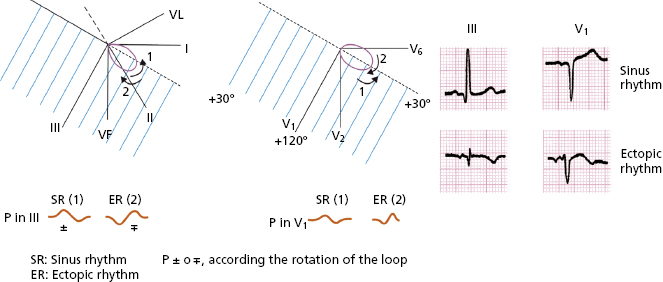
The Electrical Axis and Cardiac Rotation - Basic and Bedside Electrocardiography, 1st Edition (2009)