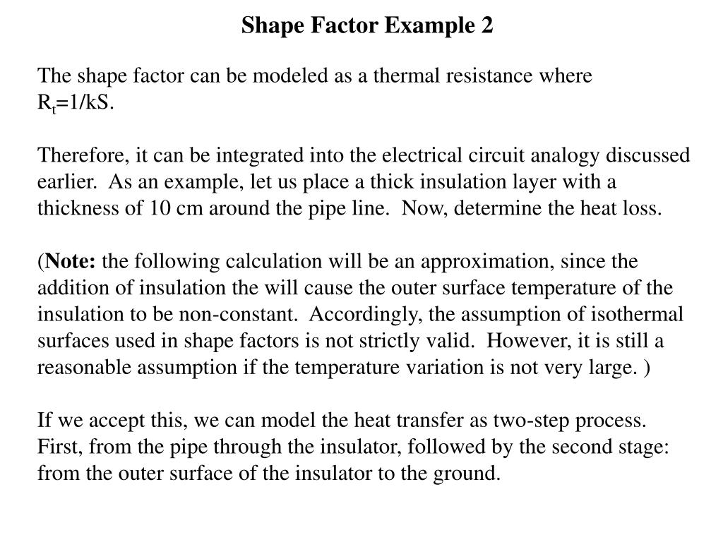
Filter Shape Factor and Selectivity
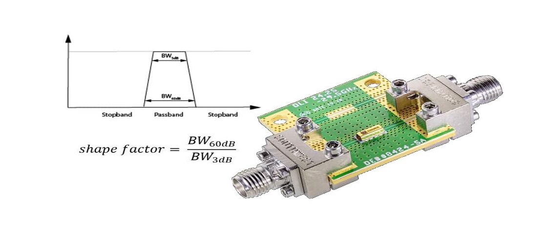
The Ideal Filter would have a unit gain (0dB) in its passband and a gain of zero (-infinity dB) in its stop band. Between the pass band and stop band, there would be no indecision and would transition from 0dB to -infinity dB asymptotically.

1 ANALOGUE TELECOMMUNICATIONS 2 MAIN TOPICS (Part I) 1)Introduction to Communication Systems 2)Filter Circuits 3)Signal Generation 4)Amplitude Modulation. - ppt download

The general frequency response shape of a bandpass filter.

Understanding The Basics Of Ceramic Coaxial Resonator Filters

The general frequency response shape of a bandpass filter.

Realization of dual-mode, high-selectivity SIW cavity bandpass filter by perturbing circular shape vias
Electronics, Free Full-Text

Filter Design Part 2. Explain the Centre Frequency, Cutoff Freq

Active Band Pass Filter - Op-amp Band Pass Filter
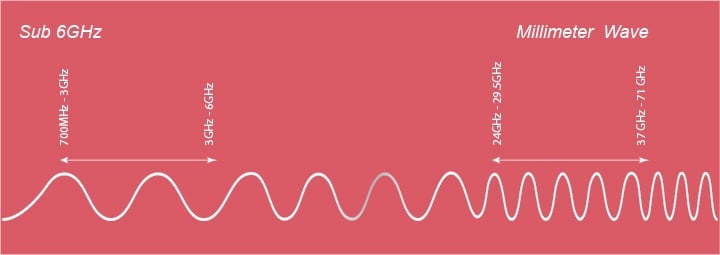
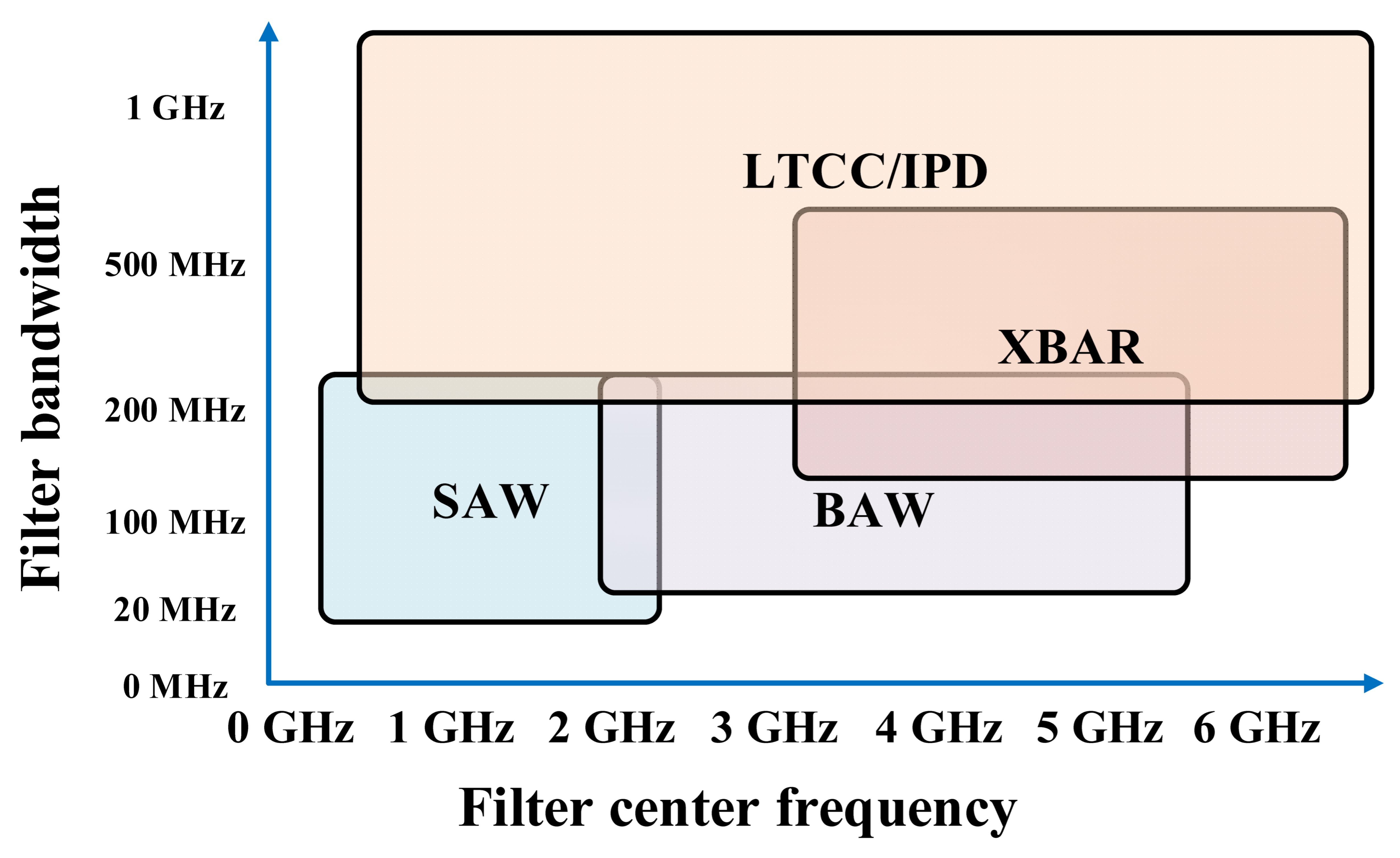
Knowles Precision Devices Filters For 5G mmWave
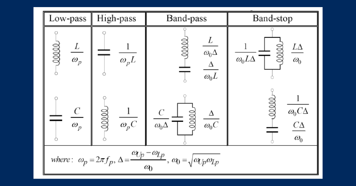
Understanding Lumped Element Filters - Mini-Circuits Blog
Filter Shape Factor and Selectivity

Bandpass Filter - an overview
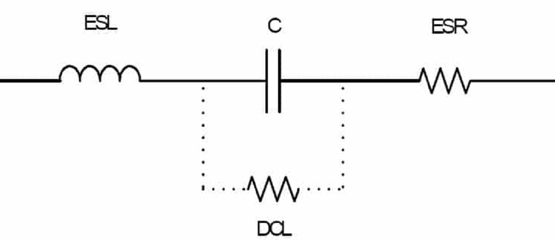
Leakage Current Characteristics of Capacitors - Case Study

Knowles Precision Devices

Knowledge Blog